Transformer Cooling Methods Explained: Why Some Work, Some Don’t, and Why It Matters in an Indian Summer
A clear, UPSC-friendly explainer on transformer cooling — the 4-letter IEC codes (ONAN/ONAF/OFAF/ODAF), the physics behind oil and air cooling, and why Indian summers push these systems to failure.
A power transformer is, at its heart, a metal box full of copper, iron and oil that asks the laws of thermodynamics for a favour every second: please carry this heat away. When the favour is denied — by a dead pump, a dust-clogged radiator, oil that has crossed its flash point, or simply by an Indian summer afternoon at 46°C with the grid demanding more than the transformer’s nameplate rating — the box stops being a transformer and becomes news. Loud, expensive, sometimes fatal news.
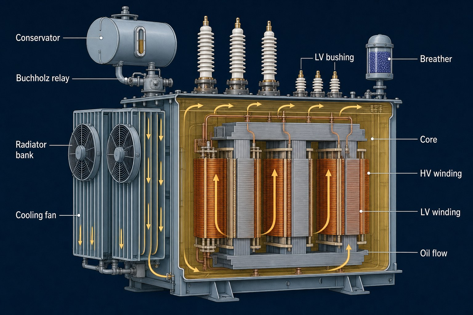
This article explains how transformers shed heat, the IEC nomenclature that classifies cooling methods, why each method works (or quietly stops working), and the specific stress factors that make Indian distribution transformers a uniquely punishing case study.
Why a transformer heats up in the first place
Three loss mechanisms turn electricity into heat inside a transformer:
Copper losses (I²R losses)
The current flowing through the windings dissipates power as heat in proportion to the square of the current. Double the current, four times the heat. This is the dominant heat source in a transformer carrying its rated load — and the reason peak-load periods are so dangerous. A 1,000 kVA transformer carrying 1,200 kVA of load is not making 20% more heat. It is making roughly 44% more heat (1.2² = 1.44).
Iron losses (core losses)
The alternating magnetic flux in the laminated steel core causes:
- Hysteresis losses — energy spent re-aligning magnetic domains 50 times per second
- Eddy current losses — small circulating currents induced in the steel laminations
Iron losses are largely constant — they depend on voltage and frequency, not on load. So a transformer drawing only its no-load current still warms up; iron losses are the floor on a transformer’s heat budget.
Stray losses
The remainder — flux leaking into tank walls, structural steel, clamping plates — typically 1-3% of total losses. Small but not negligible in large units.
The total of these losses must leave the transformer at the same rate as it is generated, or the windings will heat up indefinitely. The cooling system is what enforces that thermal equilibrium.
The three modes of heat transfer — and how a transformer uses each
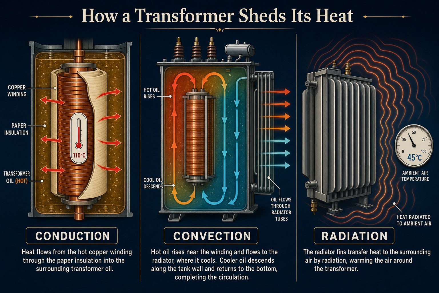
Every transformer cooling scheme exploits all three thermodynamic modes of heat transfer in series:
Conduction carries heat from the energised copper conductors through the cellulose paper insulation into the surrounding oil.
Convection carries the now-hot oil from the windings, through the bulk of the tank, and into the radiator fins on the outside.
Radiation carries heat from the radiator fins into the ambient air through electromagnetic infrared emission.
Each link in this chain has a thermal resistance. If any link weakens — say, the insulation paper carbonises after years of overheating, or the radiator fins are caked with dust — the chain breaks and the windings start cooking themselves.
The role of mineral oil
The oil in a transformer is doing two distinct jobs simultaneously: it is an electrical insulator (preventing arcing between high-voltage windings) and a coolant (the working fluid carrying heat from windings to radiators). When oil degrades — by oxidation, moisture absorption, dissolved gas accumulation, or carbonisation — it fails both jobs at once.
This dual role is why Indian utilities care so much about dissolved gas analysis (DGA) and breakdown voltage testing. A drop in oil quality is not just a maintenance metric; it is a leading indicator of impending thermal or electrical failure.
The IEC cooling-class nomenclature: the four-letter code
Every transformer cooling method is described by a four-letter code under IEC 60076-2 (the same standard is adopted as IS 2026). The letters describe, in order:
| Position | What it describes | Letter values |
|---|---|---|
| 1 | Internal cooling medium | O = mineral oil; K = insulating fluid (ester); L = non-flammable synthetic liquid; G = gas (SF₆); W = water; A = air |
| 2 | Internal circulation mechanism | N = natural; F = forced (pumped, non-directed); D = forced directed (oil pumped through windings) |
| 3 | External cooling medium | A = air; W = water; G = gas |
| 4 | External circulation mechanism | N = natural; F = forced (fans, etc.) |
So an ONAN transformer is oil-natural-air-natural — passive on both sides. An ODAF is oil-directed-air-forced — pumps inside, fans outside.
This vocabulary covers everything from a 25 kVA pole-mounted distribution transformer in a Bihar village to a 500 MVA generator transformer at a thermal power station.
The main cooling classes — what they do, where they work, when they fail
ONAN (Oil Natural, Air Natural)
The default for distribution transformers up to ~10 MVA. Oil rises by buoyancy from hot windings, flows through external radiators, and drops back into the tank. Ambient air takes heat from the radiator fins by natural convection.
Works because: the temperature difference between the hot top oil and the ambient air is enough to drive both loops without pumps or fans. No moving parts means high reliability.
Fails when: ambient temperature climbs (Indian summer pushing 45°C+), reducing the temperature differential; radiator fins are blocked by dust, vegetation, bird nests or paint flaking; the unit is overloaded so the I²R heat generation exceeds the natural convection’s carrying capacity. ONAN failure is gradual — winding temperature climbs over hours, paper insulation ages faster, and eventually a fault triggers.
ONAF (Oil Natural, Air Forced)
Add fans on the radiator side, keep the oil circulating naturally. Typically used on 5-100 MVA transformers as a “second stage” — the transformer runs ONAN at light load, and the fans kick in automatically when winding temperature exceeds a threshold (often 70-80°C).
Works because: forced air flow increases radiator heat transfer by 30-50%, giving roughly 25-33% more cooling capacity for modest added complexity (just fans + control circuit).
Fails when: fans fail and the control system either doesn’t notice (no temperature alarm) or does notice but the operator ignores the alarm. Indian distribution utilities have a documented problem with fan failures going unaddressed for weeks during peak summer.
OFAF (Oil Forced, Air Forced)
Both inside (oil pumps) and outside (fans) are forced. Used on 60-300 MVA units where natural convection cannot move enough oil through the radiator banks.
Works because: pumped oil flow rate can be 5-10× the natural-convection rate; combined with forced air, the unit can dissipate substantially more heat per unit of radiator surface.
Fails when: an oil pump fails. With OFAF, the oil flow stops being predictable when pumps fail — unlike ONAN where natural buoyancy is always available. Modern designs include redundant pumps and automatic ONAF fall-back, but older units can experience oil flow disruption during pump failure.
ODAF (Oil Directed, Air Forced)
The “D” means the oil is not just pumped — it is forced through the windings themselves via internal ducts and baffles, in a controlled flow path. Used on the largest power transformers (200 MVA and above), including most generator step-up transformers at thermal and hydro power stations.
Works because: directed flow eliminates oil-stagnant pockets near the hottest parts of the windings — the hot-spot temperature can be 10-15°C lower than in OFAF for the same total losses.
Fails when: the directing baffles or guides shift or corrode internally over decades, redirecting flow away from the hot windings. Detection requires internal inspection, which means a costly tank-opening outage.
OFWF and ODWF (Oil Forced, Water Forced; Oil Directed, Water Forced)
Water replaces air as the external coolant. Standard on generator transformers at large hydro stations and some thermal stations where cooling water is readily available.
Works because: water has roughly 3,500× the volumetric heat capacity of air. A water-cooled transformer can dissipate the same heat in a small fraction of the radiator surface.
Fails when: the heat exchanger develops an internal leak. Now water mixes with oil — and water in oil destroys insulation. Strict monitoring of cooling water pressure (must always be lower than oil pressure, so any leak goes oil-into-water, not water-into-oil) is the design safeguard.
KNAN / KNAF / KFAF (Ester-fluid variants)
The “K” prefix indicates an alternative insulating fluid — usually a natural or synthetic ester (e.g., Cargill FR3, Midel 7131). These fluids have higher flash points (~300-350°C vs ~150°C for mineral oil), are biodegradable, and are increasingly used for indoor and environmentally sensitive installations.
Works because: higher flash point reduces fire risk; biodegradability simplifies spill cleanup; ester fluids tolerate more moisture than mineral oil without breakdown-voltage collapse.
Fails when: older transformers retrofitted with ester have not been redesigned around the ester’s higher viscosity, which reduces natural-convection flow. A straight oil-to-ester swap on an ONAN unit can reduce thermal performance by 10-15%.
Why some cooling methods don’t work — the failure physics
Cooling methods don’t fail randomly. They fail because one of four bottlenecks tightens:
1. The ambient is too hot
Every cooling method is rated assuming a maximum ambient air temperature — IEC standard is 40°C as the daily average, 30°C as the yearly average. When Delhi reaches 46-48°C in May-June, transformers operating at full load are running 6-8°C hotter than their design point. Insulation life halves for every 6-8°C above rated operating temperature (a thermal-aging rule of thumb known as the Montsinger rule). A summer of overload doesn’t always cause an immediate failure; it shortens the transformer’s life from 30 years to 15.
2. The convection drive is too weak
Natural convection depends on the oil density difference between hot (top) and cold (bottom) regions of the tank. As oil ages and oxidises, its viscosity rises and the density difference per degree of temperature shrinks. ONAN units 20+ years old can lose 20-25% of their natural-convection capacity from oil ageing alone, even if everything mechanical is intact.
3. The radiator surface is blocked
Dust, paint deterioration, peeling rust, vegetation growth, and bird droppings on radiator fins reduce the effective heat-transfer area. A radiator that looks “mostly clean” to a visual inspection can have 30% reduced thermal capacity. This is why utilities specify radiator-fin cleaning as a quarterly preventive maintenance task — and why the failure to do so is the single most common cause of premature distribution transformer failure in India.
4. The active components have failed silently
Fans run on motors. Motors fail. Pumps run on motors. Motors fail. Many distribution transformer fan motors operate without remote telemetry — a fan failing in April may not be noticed until the alarm trips in June, by which point the transformer has been over-temperature for weeks.
The Indian summer problem — why distribution transformers blast
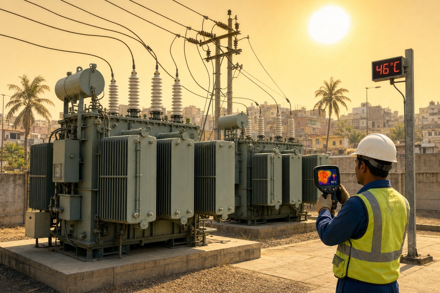
Indian distribution transformer failure rates run 12-18% per year at the worst-performing utilities (national average around 8-10%), substantially higher than the world benchmark of 1-2%. Summer is the peak.
Five compounding factors:
1. Ambient temperature routinely exceeds design rating in northern and central India during April-June.
2. Overloading during peak hours — air conditioner load surge in cities, irrigation pumpset load in agricultural feeders.
3. Voltage drop on long rural feeders forces transformers to feed reactive current, increasing copper losses.
4. Theft of cooling oil for re-use in industrial settings — leaves the transformer with reduced oil volume, less mass to absorb thermal surges.
5. Deferred maintenance — fan motors un-replaced, radiator fins un-cleaned, oil un-tested.
When a transformer blasts during summer, the immediate trigger is typically an internal short-circuit caused by insulation breakdown — but the underlying cause is months or years of cumulative thermal stress that the cooling system could not handle. The fire is the symptom; the failed cooling is the disease.
What the modern transformer carries on board
Newer Indian utility procurement (post-2020) increasingly specifies:
- Online dissolved gas analysis (DGA) sensors — continuous monitoring of hydrogen, methane, ethylene, ethane and carbon monoxide dissolved in oil. Rising gas levels signal incipient faults.
- Fibre-optic winding temperature sensors — direct measurement of the hot-spot temperature inside the windings, not just the top oil temperature.
- Smart radiator fan controllers — automatic activation based on combined winding and ambient temperature, plus failed-fan alarms to SCADA.
- Ester-fluid variants for indoor installations in commercial buildings and dense urban substations.
- Compact heat-pipe radiator banks with much higher thermal conductivity than corrugated steel fins.
These technologies don’t change the underlying physics — copper still resists current, iron still produces hysteresis losses, oil still degrades — but they shift more of the thermal management from passive design to active monitoring, catching the silent failures that traditional ONAN units cannot.
A summary table: cooling class versus typical use
| Class | Internal | External | Typical rating | Where used |
|---|---|---|---|---|
| ONAN | Oil natural | Air natural | up to 10 MVA | Distribution transformers, rural feeders |
| ONAF | Oil natural | Air forced | 5-100 MVA | Sub-transmission, large distribution |
| OFAF | Oil forced | Air forced | 60-300 MVA | Power transformers, transmission substations |
| ODAF | Oil directed | Air forced | 200 MVA+ | Generator transformers, EHV transmission |
| OFWF / ODWF | Oil forced | Water forced | 200 MVA+ | Hydro/thermal generator transformers |
| KNAN / KFAF | Ester natural/forced | Air natural/forced | up to 50 MVA | Indoor, urban, environmentally sensitive |
| GNAN | Gas (SF₆) | Air natural | special | Compact, indoor, fire-sensitive installations |
The takeaway
Transformer cooling is not a peripheral engineering detail. It is the difference between a transformer that delivers 35 years of reliable service and one that becomes a fireball in its tenth summer. Each rung of the cooling chain — conduction through paper, convection through oil, radiation from radiators — has a finite capacity, and India’s grid routinely operates at the edge of that capacity.
Understanding the four-letter IEC codes is helpful for vocabulary, but the more important habit is recognising which link in the heat chain is most likely to fail in a given installation — and designing maintenance, monitoring, and procurement accordingly. Pump motors fail more often than radiator fins. Oil degrades faster than copper. Ambient temperature does not respect nameplate ratings.
The transformer next to your colony substation is, right now, somewhere in this chain of stresses. Cooling is what stands between it and the news.
FAQs
What are the main cooling methods used in transformers?
The standard IEC-coded methods are ONAN (oil natural, air natural), ONAF (oil natural, air forced), OFAF (oil forced, air forced), ODAF (oil directed, air forced), OFWF/ODWF (oil forced/directed, water forced), and ester-fluid variants prefixed K (KNAN, KFAF). Each combines an internal cooling medium and circulation method with an external medium and method.
Why do transformers heat up at all?
Three loss mechanisms convert electricity into heat: copper losses (I²R losses in the windings, which scale with the square of current), iron losses (hysteresis and eddy currents in the laminated core), and stray losses (flux leaking into structural steel). Copper losses dominate at full load; iron losses are roughly constant.
Why is mineral oil used as a coolant in transformers?
Oil performs two jobs at once: it electrically insulates the windings from each other and from the tank (mineral oil has a dielectric strength of ~30 kV/mm), and it carries heat from windings to radiators by natural or forced convection. No single substance does both jobs as well across the temperature and voltage ranges a transformer operates in.
What causes a transformer to fail in summer?
A combination of high ambient temperature (reducing the radiator-to-air temperature differential), peak-load overcurrent (raising copper losses), aged oil (reduced convective drive), blocked radiator fins (reduced surface area), and failed fans or pumps. The fire that follows is usually triggered by insulation breakdown, but the root cause is cumulative thermal overload that the cooling system could not handle.
How does the IEC four-letter cooling code work?
Four letters describe, in order: (1) internal cooling medium — O oil, K ester, L synthetic, G gas, W water, A air; (2) internal circulation — N natural, F forced, D forced-directed through windings; (3) external cooling medium — A air, W water, G gas; (4) external circulation — N natural, F forced. So ONAN = oil natural inside, air natural outside; ODAF = oil directed inside, air forced outside.
What is the difference between OFAF and ODAF?
In OFAF, oil pumps circulate the oil through the tank, but the oil takes its own path inside (which may include stagnant zones near the hottest windings). In ODAF, the oil is directed through the windings via internal baffles and ducts — guaranteeing that the highest-loss parts of the windings get oil flow. ODAF produces a winding hot-spot temperature 10-15°C lower than OFAF for the same total losses.
Why are ester-based fluids becoming more common?
Esters (natural or synthetic) have flash points around 300-350°C (vs 150°C for mineral oil), making them substantially less fire-prone. They are biodegradable, simplifying spill cleanup. They tolerate more moisture before breakdown voltage collapses. This makes them well suited to indoor installations, commercial buildings, and environmentally sensitive sites — though their higher viscosity reduces natural-convection performance unless the transformer is designed for them.
What does “hot-spot temperature” mean and why does it matter?
The hot-spot is the single hottest point inside the transformer windings — typically near the top of the high-voltage winding, where the magnetic stray losses concentrate and oil flow is least vigorous. Insulation paper ages exponentially with hot-spot temperature: every 6-8°C above rated operating temperature halves the remaining life (the Montsinger rule). Modern transformers measure hot-spot temperature directly with fibre-optic sensors; older units estimate it from top-oil temperature plus a model.
How can transformer cooling be improved post-installation?
Five practical interventions: clean radiator fins quarterly; replace failed fan motors immediately (not after the season ends); test and replace degraded oil based on dissolved gas analysis and breakdown voltage; install online sensors (DGA, fibre-optic temperature) on the most critical units; and avoid sustained overloading — Indian utilities increasingly run distribution transformers at 80-90% of nameplate as policy, leaving headroom for the cooling system to do its job.